Building With Inductive Position Sensors: Tips and Tools
Whether you are ready to lay out your own PCB-based inductive position sensor or want to purchase a pre-built evaluation sensor for rapid system prototyping, we can assist you with your project. Our Position Sensor Library is an excellent starting point. We also offer linear and rotary evaluation board (EVB) kits to quickly prototype your system application, an Integrated Programming and Calibration Environment (IPCE), programmers and software that simplify inductive position sensor evaluation, testing and programing. If you don’t see what you need here, contact our technical support team for advanced sensor information and other assistance with your project.
Three Simple Steps for Building Your Own PCB
Step 1
Choose and download a sensor layout from the position sensors library.
Step 2
Order the matching LX3302AQPW-EASY sensor IC.
Step 3
Build and run your system. Connect with our technical support team if you need any assistance.
LX34070 90 Degree Rotary EVB
The LX34070 90-degree rotary EVB (EV65W60A), along with our free IPCE software, allows you to evaluate, auto-calibrate and customize this sensor to meet your application's requirements. The LX34070 is an excellent option for high-speed resolver applications.

Pro Sensor Kits
These kits come with your choice of an EVB, an IPCE programmer for accurate sensor measurement and programming and all the cables needed to interface the sensors and programmer to a computer. These programmers simplify designing, building and evaluating your own sensor applications.

Nano Sensor Kits
These kits speed up your time to market by combining a linear or rotary sensor with a programmable PIC18F microcontroller (MCU). Offering many of the same capabilities of the Pro kits, these are smaller reference designs that can be used in your end application.
Evaluation Boards With mikroBUS™ Connector
This evaluation board facilitates rapid system prototyping by combining a position sensor with the popular mikroBUS connector. Using this connector, you can attach the sensor to any microcontroller evaluation board that also contains this connector.

Device-Specific Evaluation Boards
Each inductive position sensor IC has several different evaluation boards to choose from. We offer EVBs for linear position sensors, angular/rotary position sensors and even redundancy. Use the provided cable to interface these boards automatically with our IPCE programmer and software.
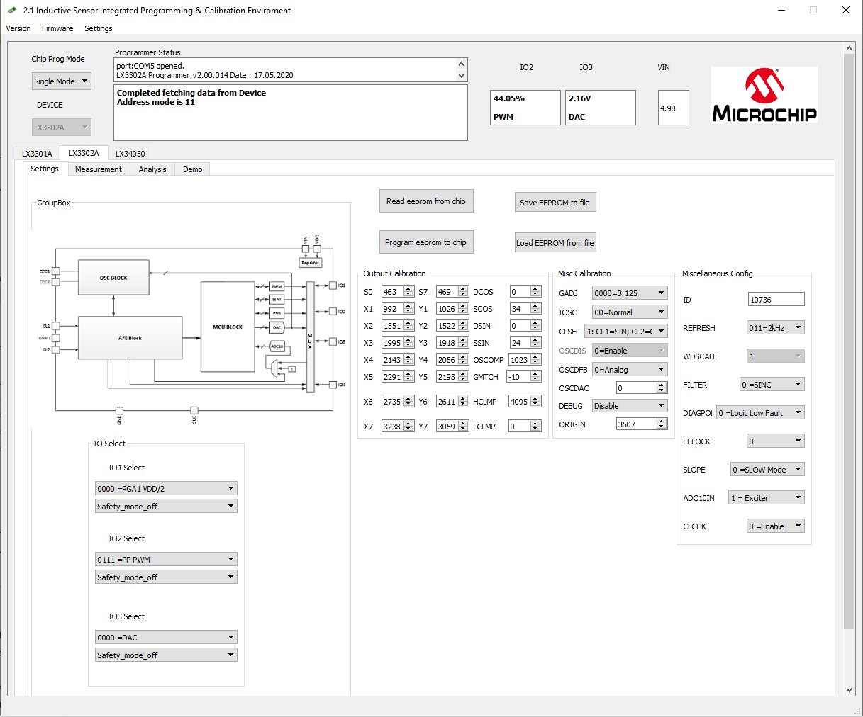
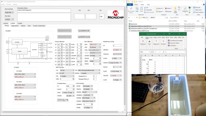
IPCE Setting Window
This window, which is the most powerful and yet simple-to-use feature of the software, provides an easy way to change the IC’s operation to meet your system requirements. You can adjust all EEPROM parameters, including I/O interface options, sampling rate and analog front end, or make small adjustments to the calibration points.
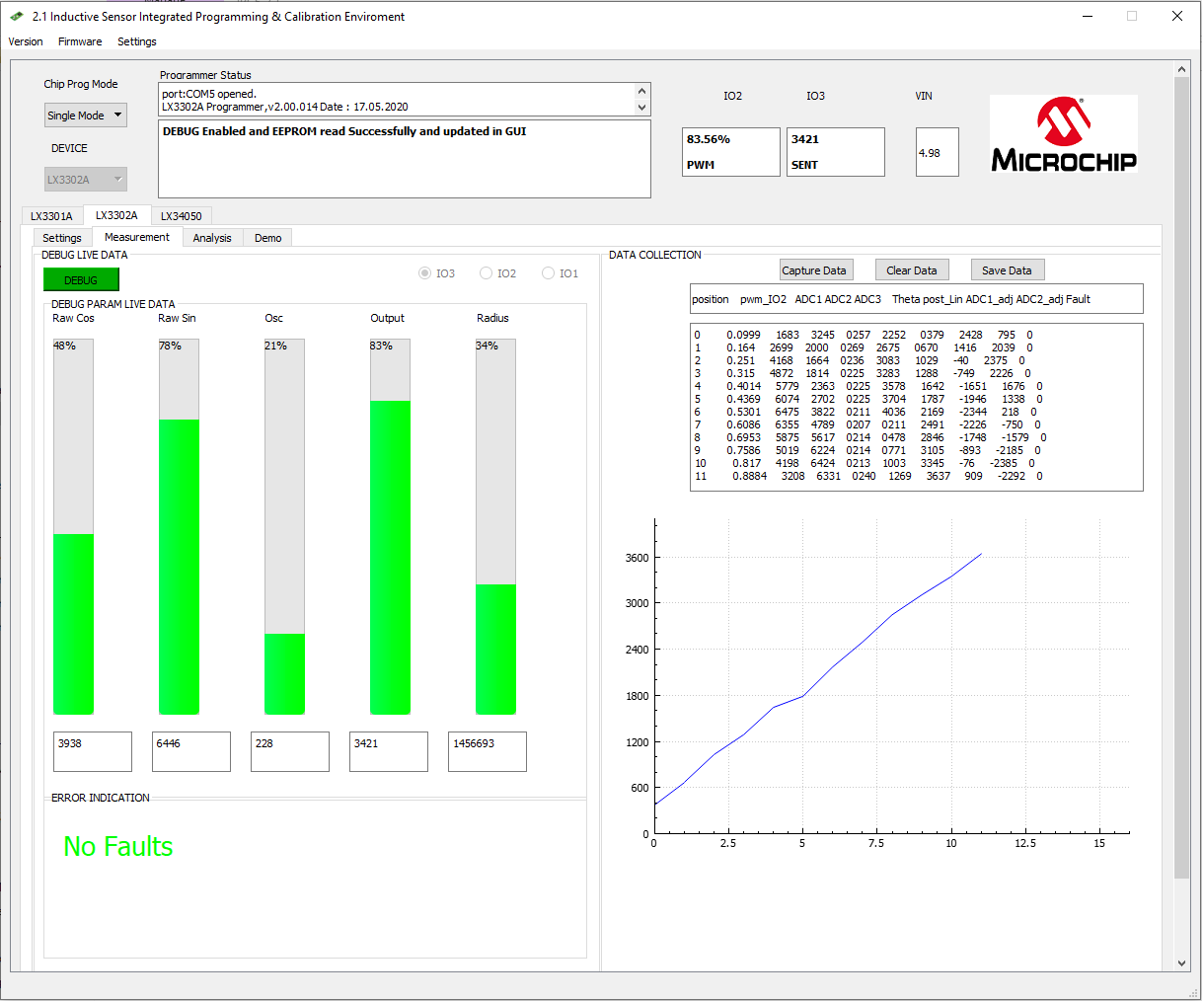
IPCE Measurement Window
Instantly capture data by clicking on the "capture data" button or do it automatically through the TCP/IP protocol. Then use the “Save Datalog” button to easily save the captured data in an Excel file. A unique sensor debug feature also allows you to capture the raw PCB sensor output, which is perfect when you want to understand how your unique mounting may be impacting the design. This mode gives you access to the internal Analog-to-Digital Converter (ADC) values, including fault diagnosis information to help you rapidly bring your sensor to production.
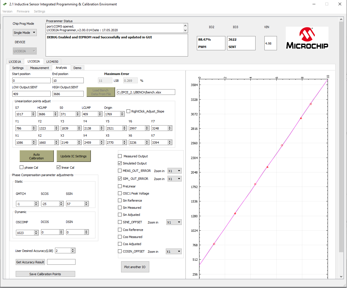
IPCE Analysis and Autocalibration Window
After measuring the sensor, use the analysis window to easily implement sensor linearization with the auto-calibration function. The software provides the optimal accuracy that can be achieved using the IC’s built-in calibration memory, or you can use an external Microchip MCU to achieve even better accuracy.

360-Degree Rotary
- Measurement range: 360 degrees
- Sensor dimensions: 12 mm diameter
- Max airgap: 1 mm
- IC: LX3302AQPW-EASY

360-Degree Rotary
- Measurement range: 360 degrees
- Sensor dimensions: 30 mm diameter
- Max airgap: 7 mm
- IC: LX3302AQPW-EASY

360-Degree Rotary
- Measurement range: 360 degrees
- Sensor dimensions: diameter of 32 mm OD/20 mm ID
- Max airgap: 2 mm
- IC: LX3302AQPW-EASY

180-Degree Rotary
- Measurement range: 180 degrees
- Sensor dimensions: 15 mm diameter
- Max airgap: 2.5 mm
- IC: LX3302AQPW-EASY

50 mm Linear
- Measurement range: 50 mm
- Sensor dimensions: 14 mm width
- Max airgap: 5 mm
- IC: LX3302AQPW-EASY

100 mm Linear
- Measurement range: 100 mm
- Sensor dimensions: 14 mm width
- Max airgap: 3 mm
- IC: LX3302AQPW-EASY

200 mm Linear
- Measurement range: 200 mm
- Sensor dimensions: 7 mm width
- Max airgap: 1.5 mm
- IC: LX3302AQPW-EASY

20-Degree Arc
- Measurement range: 20 degrees
- Sensor dimensions: 21.5 mm radius
- Max airgap: 1 mm
- IC: LX3302AQPW-EASY
Inductive Position Sensors
Tools
Inner Workings of an Inductive Position Sensor
Getting Started #1: Introduction to the Integrated Programming and Calibration Environment (IPCE)
Getting Started #1: Introduction to the Integrated Programming and Calibration Environment (IPCE)
In this video we describe the basics of operating the Integrated Programming and Calibration Environment (IPCE) software. This IPCE software, along with the LXM9518 programmer, are tools that allow you to customize, program and optimize our inductive position sensor ICs.
Getting Started #2: Auto-Calibrate Your Sensor For Improved Accuracy
Getting Started #2: Auto Calibrate Your Sensors for Improved Accuracy
This video demonstrates how to use a host microcontroller to improve the accuracy of inductive position sensors. The video uses the IPCE along with the LX3302AQPW-EASY IC and downloadable sensors to reach a desired accuracy level.
Getting Started #3: Auto-Calibrating Sensors With Externally Collected Data and Other Advanced Calibration Techniques
Getting Started #3: Auto Calibrating Sensors With Externally Collected Data
In this lesson, we show a simple step-by-step way to auto calibrate an inductive position sensor using externally collected data.
Getting Started #4: Improving Accuracy of Sensors With Microcontrollers
Getting Started #4: Improve Accuracy of Sensors With Microcontrollers
This video demonstrates how to use a host microcontroller to improve the accuracy of inductive position sensors.
Getting Started #5: Using IPCE Debug Mode to Verify Sensor Performance
Getting Started #5: Use IPCE Debug Mode to Verify Sensor Performance
In this lesson, we use the IPCE's debug mode to measure key sensor parameters like air gap range to determine how well the sensor will work in the end application.

Getting Started #6: Speed Up Your Development Time With Nano Kits for Rotary and Linear Sensors
Getting Started #6: Speed up Your Development Time With Nano Kits for Rotary and Linear Sensors
In this lesson, we introduce two new nano kits for rotary and linear inductive position sensors. These sensor kits combine an LX3302A rotary and linear sensor with a programmer that uses the PIC18 microcontroller into a small nano kit to speed up development. Run our IPCE software and plug the device into a computer using the supplied USB cable and you have a full sensor development environment. These nano kits are fully IPCE software compatible and do much of what our pro kits can do but come in a smaller package.
Video7 R2_final
Getting Started #7: Implementing Automatic Calibration With Dynamic Compensation
Unique to our inductive position sensor technology, dynamic compensation maximizes sensor accuracy over varying target-to-sensor airgap distances. Join us as we discuss the new automatic dynamic compensation calibration feature included in the IPCE software. This feature allows you to generate error profiles based on different airgap measurements that are expected to be experienced for a sensor design. The IPCE then uses these min, max and nominal air gap values to automatically generate calibration data that can be programmed into the IC.
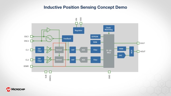
Inner Workings of an Inductive Position Sensor
Inductive Position Sensor Design Resources
Position sensing is vital to any industrial, automotive and general consumer applications. This video demo demystifies the inner workings of an inductive position sensor by taking a look at the physical, signal and mathematical models of the position sensor.
How Inductive Technology Works

How Inductive Technology Works
Our Inductive position sensors are excellent solutions for high reliability and safety-critical industrial and automotive position sensor applications, such as automobile throttle body, transmission gear sensing, electronic power steering and accelerator pedals. These unique magnetic field sensors give accurate position measurements, are immune to stray magnetic fields and don’t require an external magnetic device.
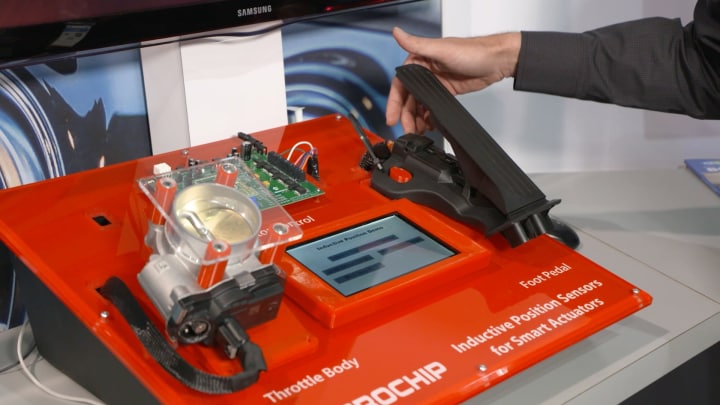
Inductive Position Sensors: Accelerator Pedal Controlled Throttle Body Smart Actuator
Inductive Position Sensors: Accelerator-Pedal-Controlled Throttle Body Smart Actuator
See two high-value applications of our inductive position sensors. In this demo, an accelerator pedal angle is measured by a dual linear position sensor and the valve of a throttle body is controlled by sensing the angle using a rotary inductive sensor. The two sensors are then combined in our MCMV 2 Motor Control Evaluation Board to bring it all together.